Engine Dimensions
Bore 3.35 in
Stroke 3.46 in
Compression Ratio 7.8 : 1
Net Horse Power
Note: Ratings are net as installed in vehicle 190 hp at 6000 rpm
Maximum Torque 203 ft.lb at 3000 rpm
System Specifications
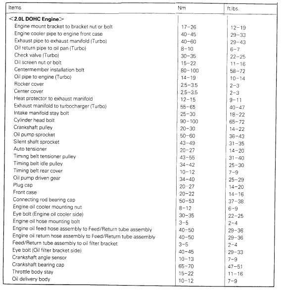
Component Tightening Specifications and Sequences
Camshaft Lobe Lift Specifications
Intake Lobe 1.3974
Exhaust Lobe 1.3858
Bearing Cap Bolt Torque
M6 Bolts 9 ft.lb
M8 Bolts 21 ft.lb
System Specifications
Cylinder Bore Diameter (Standard) 3.3465 in
Cylinder Bore Taper Maximum 0.0004 in
Cylinder Bore Out Of Round Maximum 0.0004 in
Cylinder Block Warpage Maximum 0.002 in
Balance Shaft
Journal Diameter Front Left Balance Shaft 0.7270-0.7276 in
Right Balance Shaft 1.6519-1.6526 in
Rear Left Balance Shaft 1.6126-1.6132 in
Right Balance Shaft 1.6122-1.6129 in
Oil Clearance Front Left Balance Shaft 0.0008-0.0021 in
Right Balance Shaft 0.0008-0.0024 in
Rear Left Balance Shaft 0.0017-0.0033 in
Right Balance Shaft 0.0020-0.0036 in
Connecting Rod Cap Bolts/Nuts
Connecting Rod Nuts 38 ft.lb
Connecting Rod Specifications
Side Clearance 0.0039-0.0098 in
Crankshaft Journal Tolerances
Crankshaft Main Bearing Journal Diameter 2.2433-2.2439 in
Connecting Rod Journal Diameter 1.7709-1.7715 in
Maximum Out of Round All 0.0006 in
Maximum Taper All 0.0002 in
Bearing Clearance Main Bearings 0.0008-0.0020 in
Connecting Rod Bearings 0.0008-0.0020 in
Crankshaft Endplay 0.0020-0.0070 in
Tightening Specifications
Crankshaft Main Bearing Caps 51 ft.lb
Piston Ring, Engine
Piston Ring End Gap
Note: Minimum Compression Top 0.0098 in
No.2 0.0138 in
Oil 0.0079 in
Piston Ring Side Clearance Compression 0.0012-0.0028 in
Piston, Engine
Piston Diameter (Standard)
Note: Measured at 90 angle to piston pin 3.3465 in
Piston Clearance 0.0008-0.0016 in
Service Specifications
Cylinder Head Warpage Limit 0.008 in
Cylinder Head overall thickness 5.197 in
Note: Minimum thickness is overall thickness, less warpage limit, combined with amount of grinding of cylinder block gasket surface.
Torque Specifications
Cylinder Head Bolts 72 ft.lb
Valve Cover
Cylinder Head Cover Bolts 3 ft.lb
Valve Seat
Seat Angle 44-44.5 deg
Seat Width Intake 0.035-0.051 in
Exhaust 0.035-0.051 in
Valve Spring
Free Length 1.902 in
Pressure 66 lb (US)
General Valve Specifications
Stem Diameter Intake 0.2585-0.2591 in
Exhaust 0.2571-0.2579 in
Margin
Note: Minimum Intake 0.040 in
Exhaust 0.059 in
Face Angle 45-45.4 deg
Valve Stem to Guide Clearance Specifications
Stem to Guide Clearance Exhaust 0.0020-0.0033 in
Intake 0.0008-0.0019 in
Drive Belt
Air Conditioning Belt
New 115 lbs
Used 80 lbs.
Alternator
New 132 lbs
Used 88 lbs
Intake Manifold
Intake Manifold Nuts 30 ft.lb
Oil Pump, Engine
Pump Gear To Body Clearance Drive Gear 0.0063-0.0083 in
Driven Gear 0.0051-0.0071 in
System Specifications
IDLE SPEED
Curb Idle Speed 750 +/- 100 RPM
Basic Idle Speed 750 +/- 50 RPM
Idle Speed with A/C ON:
M/T in PARK or NEUTRAL 850 RPM
A/T in DRIVE 650 RPM
TORQUE VALUES
Accelerator Cable Adjusting Bolts 3-4 lb. ft. (4-6 N-m)
Coolant Temperature Sensor 15-29 lb. ft. (20-40 N-m)
EGR Temperature Sensor 7.3-8.6 ft.lbs. (10-12 Nm)
Idle Speed Control Servo Attaching Bolts 1.8-3.3 lb. ft. (2.5-4.5 N-m)
Oxygen Sensor 30-36 ft.lbs. (40-50 Nm)
Throttle Position Sensor 1.1-1.8lb. ft. (1.5-2.5 N-m)
Throttle Body Grounding Plate (TURBO) 1.5-2 lb.ft. (2-3 N-m)
Throttle Body Mounting Bolts & Nuts 11-16 lb. ft. (15-22 N-m)
Throttle Body Stay Mounting Nut (TURBO) 7-9 lb. ft. (10-13 N-m)
Accelerator Cable Freeplay
M/T .04-.08 in. (1-2 mm)
A/T .12-.20 in. (3-5 mm)
Coolant Temperature Sensor/Switch (For Computer)
Switch Torque
Cooling Fan Switch 8-18 ft.lb
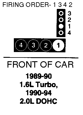
FIRING ORDER 1-3-4-2
TORQUE SPECIFICATIONS
CRANK ANGLE SENSOR MOUNTING NUT 7 - 8 lb-ft (10 - 12 Nm)
IGNITION COIL MOUNTING BOLTS 14 - 20 lb-ft (20 - 27 Nm)
SPARK PLUGS 15 - 22 lb-ft (20 - 30 Nm)
COMPRESSION PRESSURE (at 250 - 400 r/min):
Standard 1250 kPa (178 psi)
Minimum 935 kPa (133 psi)
COMPRESSION PRESSURE DIFFERENCE OF ALL CYLINDER:
Maximum 100 kPa (14 psi)
Engine Lubrication
Normal Oil Pressure 11.4 psi at 750 rpm
Fuel Pressure
Engine at curb idle
Vacuum hose connected 190 kPa (27 psi)
Vacuum hose disconnected m250 - 270 kPa (36 - 38 psi)
Compression Testing and Inspection
Before inspection, check that the engine oil, starter and battery are normal. Also, set the vehicle to the following condition: Engine coolant temperature: 80-95°C (176-203°F) . Lights, electric cooling fan and all accessories to OFF. Transaxle, Neutral (P range on vehicles with A/T). In vehicles for Canada, the headlight, tail light, etc. will remain lit even when the lighting switch is turned OFF but this is no problem.
Disconnect the spark plug cables.
Remove all of the spark plugs.
Disconnect the crankshaft position sensor connector. NOTE: Doing this will prevent the engine control unit from carrying out ignition and fuel injection.
Cover the spark plug hole with a shop towel etc., and after the engine has been cranked, check that no foreign material is adhering to the shop towel. CAUTION: Keep away from the spark plug hole when cranking. If compression is measured with water, oil, fuel, etc., that has come from cracks inside the cylinder, these materials will become heated and will gush out from the spark plug hole, which is dangerous.
Set compression gauge to one of the spark plug holes.
Crank the engine with the throttle valve fully open and measure the compression pressure. Standard value (at engine speed of 250-400 r/min): 1,250 kPa (178 psi) Limit (at engine speed of 250-400 r/min): min. 935 kPa (133 psi)
Measure the compression pressure for all the cylinders, and check that the pressure differences of the cylinders are below the limit. Limit: max difference. 100 kPa (14 psi)
If there is a cylinder with compression or a compression difference that is outside the limit, pour a small amount of engine oil through the spark plug hole, and repeat the operations in steps 7 and 8. If the compression increases after oil is added, the cause of the malfunction is a worn or damaged piston ring and/or cylinder inner surface. If the compression does not rise after oil is added, the cause is a burnt or defective valve seat, or pressure is leaking from the gasket.
Connect the crankshaft position sensor connector.
Install the spark plugs and spark plug cables.
Use the scan tool to erase the diagnostic trouble codes, or disconnect the negative battery cable for more than 10 seconds and reconnect it. NOTE: This will erase the diagnostic trouble code resulting from the crankshaft position sensor connector being disconnected.
Differential Carrier Inspection Procedures
Raise and support vehicle.
Disconnect driveshaft at companion flange, refer to Transmission and Drivetrain/Drive/Propeller Shafts, Bearings and Joints/Service and Repair.
Remove caliper assembly and suspend with wire.
Attach a spring balance to hub bolt, then pull balance at a right angle to bolt. Measure rotation starting torque.
If rotation starting torque is less than 6 lb-in, bearing is satisfactory.
If rotation starting torque is more than 6 lb-in, ensure tightening torque of axle shaft companion flange is 116-159 lb-ft , on Eagle Talon and 137 lb-ft , on Stealth models less turbo or 188-217 lb-ft , on Stealth models with turbo. If torque is satisfactory, replace wheel bearing
Exploded View Of Differential Carrier (W/Limited Slip Differential)
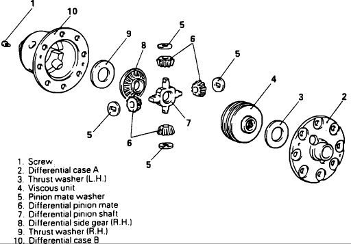
Remove attaching screw from differential case A.
Remove differential case B.
Remove left thrust washer. NOTE: Since thrust washer from left side is of a different thickness than the right side, it will be necessary to mark the washer in some manner for assembly reference.
Remove viscous unit, pinion mate washer, differential pinion mate, pinion shaft and righthand differential side gear.
Remove right thrust washer. NOTE: Since thrust washer from right side is of a different thickness than the left side, it will be necessary to mark the washer for assembly reference.
Component locations
A/C Control Unit: Under RH Side Of I/P, Above Heater Assembly
Air Conditioner Relay Box: LH Side Of Engine Compartment Cowl, Near Strut Tower
Air Flow Sensor (1.8L): In Air Filter Assembly
Air Flow Sensor (2.0L): RH Front Corner Of Engine Compartment, In Air Filter Assembly
Air Inlet Sensor: RH Side Of I/P, Above Heater Assembly
Air Thermo Sensor: RH Side Of I/P, Above Heater Assembly
Alternator Relay: RH Side Of Engine Compartment, Front Of Strut Tower
Auto-Cruise Control Unit: Behind LH Side Of I/P, Left Of Steering Column
Auto-Cruise Control Actuator: RH Side Of Engine Compartment
Automatic Seat Belt Relay (RH): Behind Rear RH Quarter Trim Panel
Automatic Transaxle Fluid Temperature Sensor: Below Relay Center, On Transaxle
Back-Up Lamp Switch (1.8L W/Manual Trans): Front RH Side Of Transaxle
Barometric Pressure Sensor (2.0L Turbo): RH Front Corner Of Engine Compartment, In Air Filter Assembly
Brake Fluid Level Sensor: LH Rear Corner Of Engine Compartment, On Cowl
Buzzer: Under Center Of I/P, Left Of Radio Assembly
Coolant Temperature Sender Unit (1.8L): Upper RH Side Of Engine, Near Thermostat Housing 1
Coolant Temperature Sensor (1.8L): Upper RH Side Of Engine, Near Thermostat Housing
Coolant Temperature Sensor (2.0L Turbo): Upper RH Side Of Engine, Near Thermostat Housing
Coolant Temperature Switch (2.0L): Upper RH Side Of Engine, Near Thermostat Housing
Condenser Fan Motor Relay: LH Side Of Engine Compartment Cowl, Near Strut Tower
Condenser High-Low Changeover Relay: LH Side Of Engine Compartment Cowl, Near Strut Tower
Crankshaft Angle Sensor (1.8L): LH Side Of Engine, On Intake
Crankshaft Angel Sensor (2.0L Turbo): Upper RH Side Of Engine, Near Thermostat Housing
CRC Filter (1.8L): LH Side Of Engine, On Intake
Detonation Sensor (2.0: Turbo): Top Center Of Engine, Near Valve Cover
Defroster Relay: RH Side Of Engne Compartmet Cowl, Near Strut Tower
Defroster Timer: Under LH Side Of I/P, Left Of Steering Column
Diagnostic Connector: Under LH Side Of I/P, Near Kick Panel
Door Ajar Warning Light Diode: Below LH Sill Plate
Door Lock Relay: RH Side Of Engine Compartment
Door Lock Control Unit: RH Side Of Passenger Compartment, Behind Kick Panel
Door Latch Switch: In Driver's Seat
Dome Lamp Relay: Behind Rear LH Quarter Trim Panel
Dual Pressure Switch: RH Side Of Engine
EGR Control Solenoid (1.8L): Top Center Of Engine Compatment Cowl
EGR Control Solenoid Valve (2.0L: Turbo): Rear LH Side Of Engine Compartment, Near Strut Tower
EGR Temperature Sensor (1.8L): Top Center Of Engine, Near Intake
EGR Temperature Sensor (2.0L Turbo): Top Center Of Engine, Near Intake
Engine Control Unit: Under Center Of I/P, Behind Console
Fog Lamp Relay: RH Side Of Engine
Fuel Pump Check Terminal (2.0L Turbo): On Engine Compartment Cowl, Near Battery
Fuel Pressure Control Valve (2.0L Turbo): Rear LH Side Of Engine Compartment, Near Strut Tower
Hazard & Turn Flashers: On Junction Block, Behind LH Side Of Dash Panel
Headlamp Relay: RH Side Of Engine
Heater Relay: Under LH Side Of I/P, Left Of Steering Column
Idle Switch (1.8L): Top RH Side Of Engine, On Intake
Idle Switch (2.0L Turbo): Top RH Side Of Engine, On Throttle Body
Inhibitor Switch (1.8L): Front RH Side Of Transaxle
Ignition Coil (1.8L): LH Side Of Engine, On Intake
Ignition Coil (2.0: Turbo): Rear LH Side Of Engine, Near Strut Tower
Ignition Timing Adjustment Terminal (2.0LTurbo): On Engine Compartment Cowl, Near Battery
ISC Servo (1.8L): Top RH Side Of Engine, On Intake
ISC Servo (2.0L): Top RH Side Of Enigne, On Intake
Intake Air Temperature Sensor (2.0L Turbo): RH Front Corner Of Engine Compartment, In Air Filter Assembly
Intermittent Rear Wiper Relay: Behind Rear LH Quarter Trim Panel
Kickdown Servo Switch: RH Side Of Engine Compartment, Below Relay Center
Magnetic Clutch Relay: LH Side Of Engine Compartment Cowl, Near Strut Tower
Motor Position Sensor (1.8L): Top RH Side Of Engine, On Intake
MPI Control Relay: Center Of I/P, Below Radio
MPI Control Unit: Center Of I/P, Below Radio
Noise Condenser: Behind Rear LH Quarter Trim Panel
Oil Pressure Gauge Sender (1.8L): Rear LH Side Of Engine
Oil Pressure Switch (1.8L): Rear LH Side Of Engine
Oxygen Sensor (1.8L): Front Of Engine, On Exhaust Manifold
Oxygen Sensor (2.0L Turbo): Front Of Engine, On Exhaust Manifold
Oxygen Sensor Check Connector: RH Side Of I/P, Near Kick Panel
Pulse Generator A: RH Side Of Engine Compartment, On Transaxle Housing
Pulse Generator B: RH Side Of Engine Compartment, On Transaxle Housing
Purge Control Solenoid Valve (1.8L): Top Center Of Engine Compartment cowl
Pop-Up Motor Relay: RH Side Of Engine compartment, Front Of Strut Tower
Power Steering Fluid Pressure Switch (1.8L): Lower LH Side Of Engine, On Power Steering Pump
Power Steering Fluid Pressure Switch (2.0L Turbo): Lower LH Side Of Engine, On Power Steering Pump
Power Transistor (1.8L): LH Side Of Engine, On Intake
Power Transistor (2.0L Turbo): Rear LH Side Of Engine, Near Strut Tower
Power Window Relay: RH Side Of Engine Compartment, Front Of Strut Tower
Radiator Fan Motor Relay: RH Side Of Engine Compartment, Front Of Strut Tower
Radiator Water Level Switch: RH Side Of Engine Compartment, On Radiator
Relay Center: RH Side Of Engne Compartment, Front Of Strut Tower
Seat Belt Fasten Switch: In Automatic Seat Guide Rail, In LH B-Pillar
Seat Belt Release Switch: In Automatic Seat Guide Rail, Near Whindshield
Starter Relay: Under LH Side Of I/P, Left Of Steering Column
TDC Sensor (1.

: LH Side Of Engine, On Intake
TDC Sensor (2.0L Turbo): Upper RH Side Of Engine, Near Thermostat Housing
Theft-Alarm Control Unit: Under RH Side Of I/P
Throttle Position Sensor (1.8L): Front RH Top Of Engine, Near Valve Cover
Throttle Position Sensor (2.0L Turbo): Top RH Side Of Engine, On Throttle Body
Vehicle Speed Sensor: In Speedometer Gauge
Waste Gate Control Valve (2.0L Turbo): Front RH Corner Of Engine Compartment, Near Air Filter Assembly
4-Speed Automatic Transaxle Control Unit: RH Side Of I/p, Near Console
4-Speed Automatic Transaxle Control Solenoid Valve (1.8L): Front RH Side Of Transaxle
A-Z Ground List
Body To Engine: Center Of Engine, Near Valve Cover
Body To Transaxle: RH Side Of Engine Compartment, Below Relay Center
Body To Battery: Rear RH Side Of Engine Compartment, Near Battery
Ground 2: Front LH Side Of Engine Compartment
Ground 3: Front RH Side Of Engine Compartment, Near Relay Center
Ground 6: Behind RH Side Of I/P, Right Of Glove Box
Ground 7: Behind Center Console, Below Battery
Ground 8: LH Side Of Passenger Compartment, Behind Kick Panel
Ground 9: On Rear Center Panel In Luggage Compartment
Ground 11: Behind Rear LH Quarter Panel
Ground 12: Behind Rear RH Quarter Panel
Diagnosis Connector Terminals

Ignition Cable
[/img]
http://i1133.photobucket.com/albums/m59 ... dddddd.gif[/img]
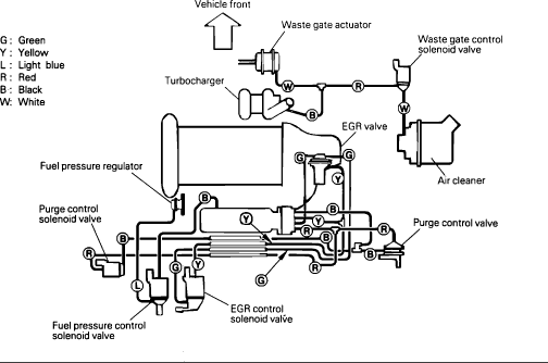
Emissions Control Vacuum Routing For Turbocharged California Vehicles
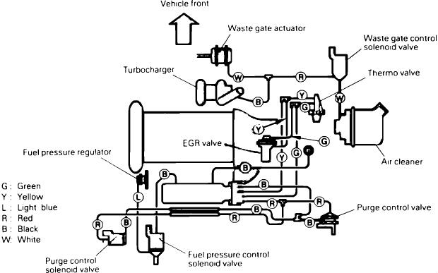
Emissions Control Vacuum Routing For Turbocharged Non-California Vehicles
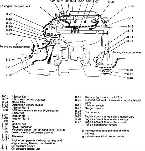
Transaxle Harness Connections
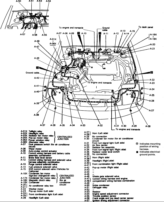
Engine Compartment Harness Connections For Turbo Models
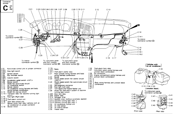
I/P Connector Locations
Ignition System Firing Order
Timing Belt
Remove lower left engine compartment splash shield.
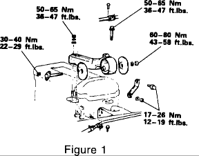
Support engine with engine support fixture, tool # C-4852 or # 7137, and remove the left engine mount and bracket Fig. 1.
NOTE:
Loosen water pump pulley bolts before removing belt.
Loosen the water pump pulley bolts. Remove the alternator/water pump drive belts, and the power steering drive belt.
Remove water pump pulley.
Remove the tensioner pulley bracket and the A/C belt.
Remove crankshaft pulley.
Remove the upper and lower timing belt covers.
Rotate the crankshaft clockwise and align the timing marks so as to bring the No. 1 piston to the Top-Dead-Center (TDC) position of the compression stroke.
Caution:
Rotate the crankshaft in a clockwise direction.
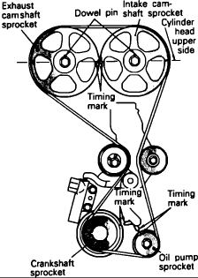
The camshaft sprocket dowel pins must be at the 12 o'clock position and the camshaft sprocket timing marks must be aligned together (left sprocket at the 3 o'clock and right sprocket at the 9 o'clock positions). Both camshaft sprocket timing marks must be in line with the top surface of the cylinder head Fig. 54. [A straight edge (ruler) laid across the center of the camshaft attaching bolts will help you to better see and align the timing marks.] The crankshaft and oil pump sprockets must also be aligned with their respective timing marks Fig. 54.
NOTE:
CRANKSHAFT MAY NEED TO BE ROTATED UP TO SIX TURNS BEFORE ALL SPROCKETS ARE PROPERLY ALIGNED AND THE REAR BALANCE SHAFT IS IN PHASE, DUE TO THE OIL PUMP - TO BALANCE SHAFT GEAR RATIO.
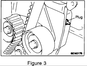
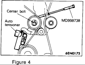
Remove rubber plug from inner timing belt cover and screw special tool no. MD998738 into the engine left support bracket until it makes contact with the tensioner arm Fig. 3 & 4.
Loosen the tensioner pulley center bolt Fig. 4.
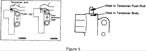
Compress the Auto Tensioner push rod by SLOWLY rotating special tool no. MD998738 until hole in Auto Tensioner push rod aligns with the hole in the Auto Tensioner body Fig. 5.
NOTE:
PUSH ROD MAY NEED TO BE ROTATED IF HOLE IN ROD IS NOT VERTICALLY IN LINE WITH HOLE IN HOUSING.
Insert a 1/16 inch allen wrench or similar pin (1.4 mm (.055 in.) in diameter) into the aligned holes to hold the push rod in the reset (pinned) position. Back off special tool MD998738 once auto tensioner is in the reset position Fig. 5.
NOTE:
INSPECT THE TENSIONER AND REPLACE IT IF IT SHOWS SIGNS OF OIL LEAKAGE.
Remove and discard the camshaft timing belt.
Removal of Timing Belt "B"
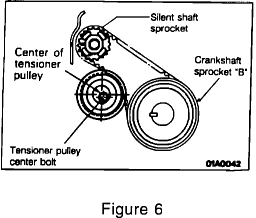
Loosen timing belt "B" tensioner pulley center bolt Fig. 6.
Remove and discard timing belt "B".
Installation of Timing Belt "B"
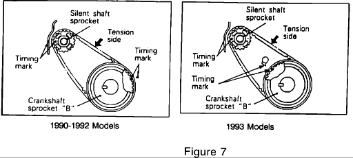
Ensure that the crankshaft sprocket and the silent shaft sprocket timing marks are aligned. Install new timing belt "B" over crankshaft sprocket "B", around the tensioner pulley, and over the silent shaft sprocket. Do not leave any slack on the tension side of the belt Fig. 7.
Push the timing belt "B" tensioner up to place pressure on the timing belt so that the tension side is taut. Belt tension should be 5-7 mm (.20-.28 in.) using the belt deflection method. Tighten the tensioner center bolt and torque to 15-22 Nm (11-16 ft.lbs.) Fig. 7.
CAUTION:
WHEN TIGHTENING THE BOLT, ENSURE THAT THE TENSIONER PULLEY SHAFT DOES NOT ROTATE WITH THE BOLT. ALLOWING IT TO ROTATE CAN CAUSE EXCESSIVE TENSION ON THE BELT.
CAMSHAFT TIMING BELT:
Rotate the camshaft timing belt tensioner pulley so that the pinholes are to the left of the center bolt. Tighten the center bolt finger-tight Fig. 4.
NOTE:
LEAVE THE ALLEN WRENCH INSTALLED IN THE AUTO TENSIONER.
Make sure the camshaft sprocket dowel pins are located at the 12 o'clock position and the camshaft sprocket timing marks are aligned together (left sprocket at the 3 o'clock and right sprocket at the 9 o'clock positions). Both camshaft sprocket timing marks should be in line with the top surface of the cylinder head Fig. 54.
NOTE:
THE EXHAUST CAMSHAFT SPROCKET MAY ROTATE IN THE COUNTERCLOCKWISE DIRECTION. THIS SHOULD BE CONSIDERED WHEN INSTALLING THE TIMING BELT.
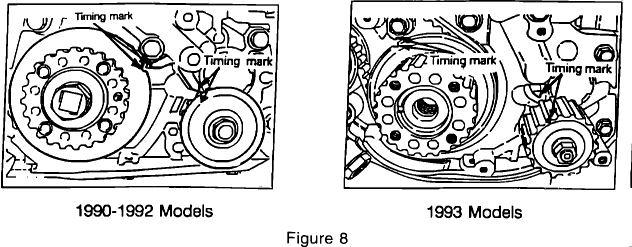
Make sure that the crankshaft sprocket and the oil pump sprocket is aligned with the timing mark pointers Fig. 8.
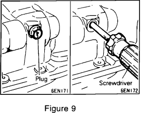
Remove the balance shaft plug on the rear side of the cylinder block and insert a Phillips screwdriver (shank diameter 8 mm (.31 in.)) through the hole. The balance shaft is in the correct position if the screwdriver can be inserted at least 60 mm (2.4 in.). If the inserted depth is less than this, only 20-25 mm (.8-1.0 in.), the oil pump sprocket must be rotated one full turn and timing marks realigned. Recheck the balance shaft position using the screwdriver to ensure that it can be inserted 60 mm (2.4 in.) or more. Keep the screwdriver inserted until timing belt installation is complete Fig. 9.
CAUTION:
MAKE SURE THE BALANCE SHAFT IS PROPERLY POSITIONED. It is possible for the oil pump sprocket timing marks to be properly aligned, and have the balance shaft out of phase. This could result in a SEVERE engine vibration.

Install the new timing belt over the intake side camshaft sprocket and clamp it in position with a clip Fig. 10.
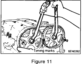

Use a wrench to maintain alignment of the two camshafts and install the timing belt over the exhaust side sprocket, aligning the timing marks as shown in Figure 2 and clamp the belt in position with a clip Fig. 11 & 12.

Position the timing belt around the idler pulley, oil pump sprocket, crankshaft sprocket and tensioner pulley (in that order) as shown in Fig. 13.

Rotate the tensioner pulley in a clockwise direction and tighten the center bolt Fig. 14.
NOTE:
MAKE SURE ALL TIMING BELT TEETH ARE ENGAGED WITH THE TEETH ON THE CAMSHAFTS, OIL PUMP, AND CRANKSHAFT SPROCKETS AND THAT ALL TIMING MARKS ARE STILL PROPERLY ALIGNED.
Remove the screwdriver from the balance shaft hole and install the plug.
Remove the two clips holding the belt to the camshaft sprockets.
Rotate the crankshaft a 1/4 turn counterclockwise, then rotate it clockwise until the timing marks are aligned again. Crankshaft position should still be at the No. 1 cylinder TDC position of the compression stroke.
NOTE:
MAKE SURE THAT ALL OF THE TIMING MARKS ARE STILL ALIGNED.

Loosen the tensioner pulley center bolt, attach special tool no. MD998767 (or MD998752) and apply2.7 Nm (24 in.lbs.) torque to pulley (with beam type torque wrench) as shown in Fig. 15. WITH TORQUE APPLIED TO THE TENSIONER PULLEY, tighten the attaching bolt, then torque to49 +/- 6 Nm (36 +/- 4 ft.lbs.).
Caution:
Failure to follow this procedure will cause the belt tension to exceed the range of the auto tensioner limits and result in premature timing belt failure or jumping.
NOTE:
IF THE VEHICLE BODY INTERFERES WITH THE SPECIAL TOOL AND THE TORQUE WRENCH, RAISE THE ENGINE UP SLIGHTLY UNTIL THERE IS ADEQUATE CLEARANCE.

SLOWLY rotate the special tool no. MD998738 until it makes contact with the tensioner arm and remove the allen wrench from the auto tensioner Fig. 16.
Back off the special tool and rotate the crankshaft SIX complete turns clockwise.

Measure the auto tensioner push rod position with a drill bit (distance between the tensioner arm and auto tensioner body) to ensure that it falls within the specification of 3.8-4.5 mm (.15-.18 in.) as shown in Fig. 17.
NOTE:
WAIT 15 MINUTES AFTER THE ALLEN WRENCH IS REMOVED FROM AUTO TENSIONER (FOR PLUNGER ROD TO STABILIZE) BEFORE MEASURING. IF THE PLUNGER ROD IS OUT OF SPECIFICATION, RESET THE AUTO TENSIONER (STEPS 10, 11 AND 12) AND REPEAT STEPS 29 THROUGH 32 UNTIL THE SPECIFIED VALUE IS OBTAINED.
Remove special tool no. MD998738 and install the rubber plug to the inner timing belt cover.

Install the upper and lower timing belt covers as shown in Fig. 18. (Rotate the bottom of the lower cover toward the rear to assist in clearing the water pump).
NOTE:
THE TIMING COVER BOLTS VARY IN LENGTH. MAKE SURE THAT THE PROPER SIZE BOLTS ARE INSTALLED IN THE CORRECT HOLE LOCATIONS Fig. 18.
Install crankshaft pulley and torque to 25 +/- 5 Nm (18 +/- 4 ft.lbs.).
Install A/C tensioner bracket with A/C belt and torque to 25 +/- 2 Nm (18-4 ft.lbs.) Adjust belt tension to 5.5-6.0 mm (.220-.240 in.) belt deflection.
Install water pump pulley.
Install alternator/water pump and power steering drive belts and adjust belt tension as follows:
Belt Deflection
Alternator/Water Pump Belt 9.0-11.5 mm (.354-.453 in.)
Power Steering Belt 6.0-9.0 mm (.240-.354 in.)

Install left front engine mount and bracket and torque to the specifications shown in Fig. 19.
Remove engine support fixture.
Install lower engine compartment splash shield.
Wheel alignment
Prior to wheel alignment, ensure tires are at recommended pressure, are of equal size and have approximately the same wear pattern. Check front wheel and tire assembly for radial runout and inspect lower ball joints and steering linkage for looseness. Check front and rear springs for sagging or damage. Front suspension inspections should be performed on a level floor or alignment rack with fuel tank at capacity and vehicle free of luggage and passenger compartment load. The vehicle should be bounced an equal number of times from the center of the bumper alternately, first from the rear, then the front, releasing at the bottom of down cycle.
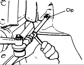
Adjust toe-in by undoing clips and turning each tie rod turnbuckle an equal amount in opposite directions. Toe will move out as the left turnbuckle is turned toward front of vehicle and the right turnbuckle is turned toward rear of vehicle. For each half turn, toe-in will increase or decrease 0.24 inch.
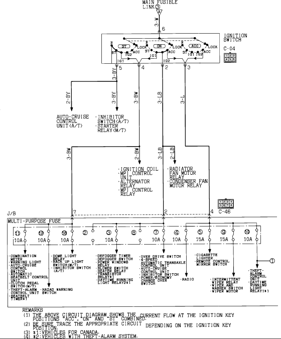
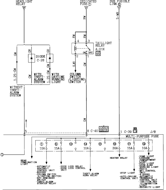
Fuse Panel Details
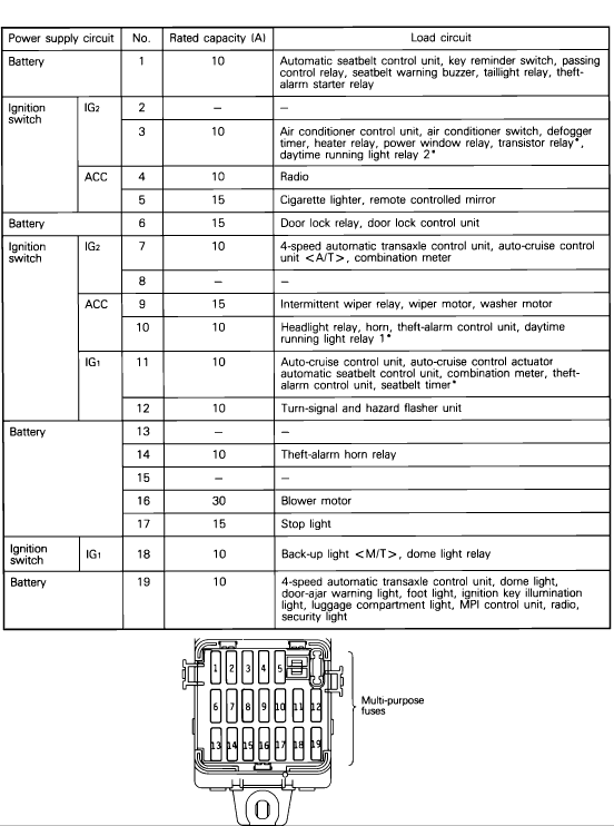
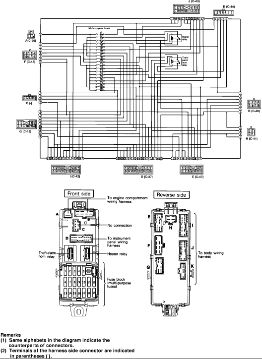
Power Distribution
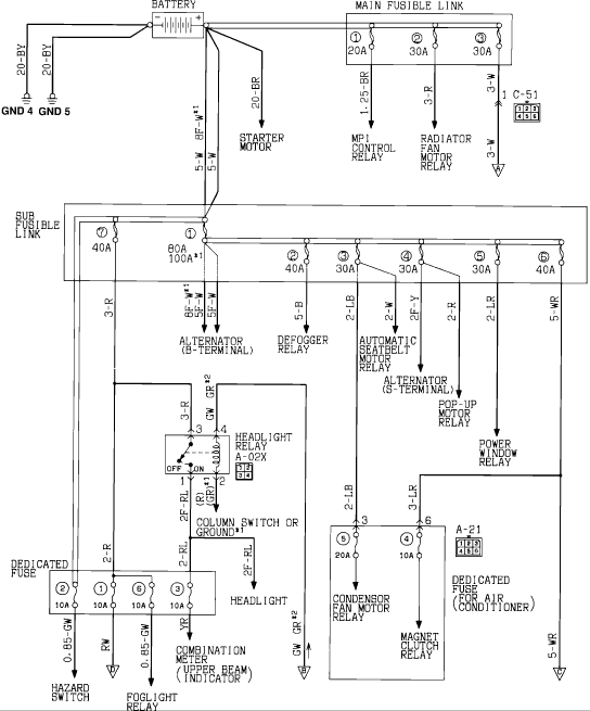
Cylinder Head Removal
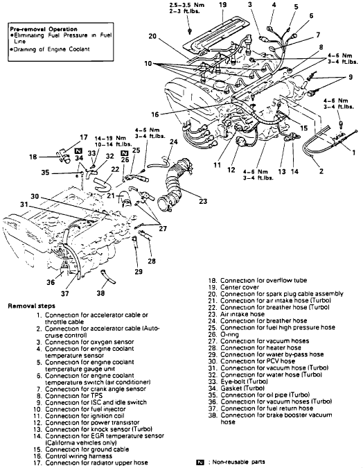
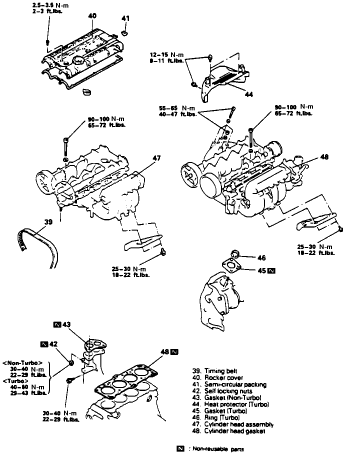
Remove cylinder head in numbered sequence, Fig. 20, noting the following:
Before disconnecting high pressure fuel line, relieve fuel system pressure as follows:
Disconnect fuel pump harness connector at fuel tank.
Start engine and let it run until it stalls, then turn ignition switch to off.
Disconnect negative battery cable.
Reconnect fuel pump harness connector.
Cover fuel line connection with rags to prevent spraying of fuel during disconnection.
Before removing upper radiator hose, mark hose clamp in relation to hose for assembly reference, then drain coolant as follows:
Place instrument panel temperature control lever in Hot position.
Carefully remove radiator cap.
Remove radiator drain plug.
Refer to TIMING BELT when removing timing belt.
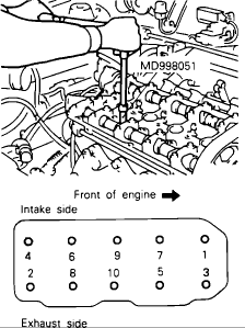
Using cylinder head bolt wrench No. MD998051 or equivalent, remove cylinder head bolts in sequence as shown in Fig. 21.
INSTALLATION
Reverse removal procedure to install, noting the following:
Install cylinder head gasket as follows:
Using a suitable scraper, remove old gasket material from cylinder block, using care not to allow old gasket material to fall into cylinder or passages.
Clean head and block surfaces that come in contact with head gasket.
Place head gasket on block with identification mark at top front. Do not apply sealant to head gasket.
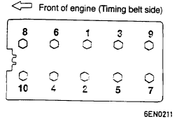
Fig. 22 Head Bolt Tightening
Head Torque sequence
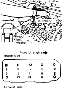
When installing cylinder head, install head bolt washers, then torque head bolts to 65-72 ft.lbs.(90-100 Nm) in two or three steps and in order as shown in Fig. 22.
When installing semi-circular packing, apply liberal amount of gasket sealant onto circumference of packing.
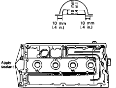
When installing rocker cover, apply gasket sealant to area as shown in Fig. 23.
Refer to TIMING BELT when installing timing belt.
When installing high pressure fuel line (5), apply small amount of gasoline to hose union. Use care to avoid damaging O-ring.
Camshaft Assembly
REMOVAL
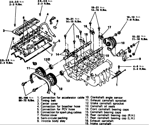
Remove camshaft in numbered sequence, Fig. 67, noting the following:
Remove timing belt, refer to TIMING BELT .
Remove camshaft sprockets as follows:
While holding camshaft in position with a crescent wrench at hexagon between No. 2 and No. 3 journals, remove camshaft sprocket bolt.
Remove camshaft sprockets.
Remove camshaft oil seals using a suitable screwdriver.
Remove camshaft bearing caps by loosening installation bolts in two or three steps. If bearing cap is difficult to remove, gently tap on the rear portion of the camshaft with a plastic hammer.
INSTALLATION
Reverse removal procedure to install, noting the following:
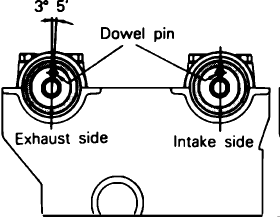
Install the camshafts on the cylinder head. Ensure intake side camshaft is installed on intake side and exhaust side camshaft is installed on exhaust side. Intake side camshaft has a slot machined in the back end to drive the crank angle sensor. Once installed, the camshaft dowel pins should be in the positions as shown in Fig. 68.
When installing camshaft bearing caps, tighten evenly, in two or three steps.
Installing Camshaft Oil Seal.
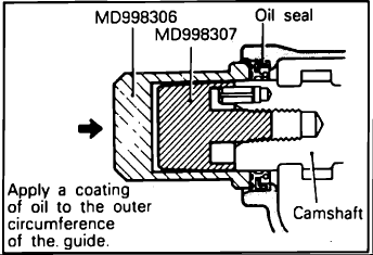
When installing camshaft oil seal, use oil seal guide tool No. MD998307 and oil seal installation tool No. MD998306 or equivalents as shown, Fig. 69.
Install crank angle sensor as follows:
Ensure mating mark on housing of crank angle sensor is aligned with notch in plate.
Ensure crank angle sensor does not move when tightening attaching nut.
Installing Rocker Cover.
When installing semi-circular packing, apply liberal amount of gasket sealant onto circumference of packing.
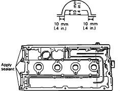
When installing rocker cover, apply gasket sealant to area as shown in Fig. 23.
PISTON AND CONNECTING ROD ASSEMBLY REMOVAL
Remove top ridge of cylinder bores with a reliable ridge reamer before removing pistons from cylinder block. Be sure to keep tops of pistons covered during this operation . Mark piston with matching cylinder number.
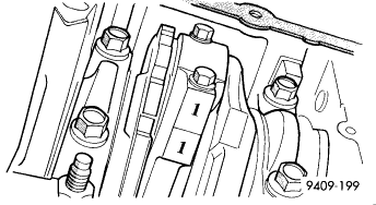
Remove oil pan. Scribe the cylinder number on the side of the rod and cap for identification.
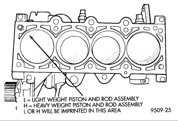
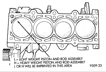
Pistons have stamping in the front half of the piston facing towards the front of engine. The stamping is a weight identification for the assembly L is for light and H is for heavy. These assemblies should all be the same weight class. Service piston assemblies are marked with a S and can be used with either L or H production assemblies.
Pistons and connecting rods must be removed from top of cylinder block. Rotate crankshaft so that each connecting rod is centered in cylinder bore.
Remove connecting rod cap bolts. Push each piston and rod assembly out of cylinder bore. Be careful not to nick crankshaft journals.
After removal, install bearing cap on the mating rod.
Piston and Rods are serviced as an assembly.
INSTALLATION
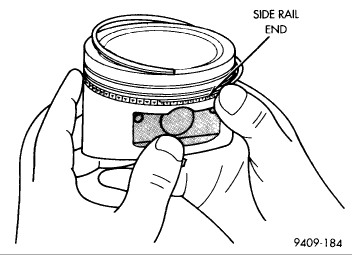
Before installing pistons and connecting rod assemblies into the bore, be sure that compression ring gaps are staggered so that neither is in line with oil ring rail gap.
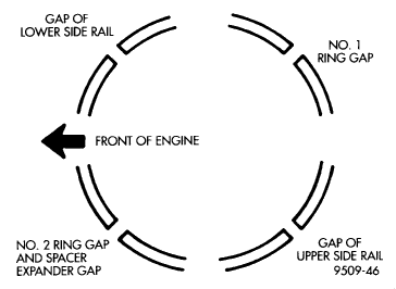
Before installing the ring compressor, make sure the oil ring expander ends are butted and the rail gaps
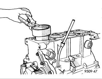
Immerse the piston head and rings in clean engine oil, slide the ring compressor, over the piston. Be sure position of rings does not change during this operation.
The weight stamp designation L for light or H for heavy assembly will be in the front half of the piston facing toward the front of the engine.
Rotate crankshaft so that the connecting rod journal is on the center of the cylinder bore. Insert rod and piston assembly into cylinder bore and guide rod over the crankshaft journal.
Tap the piston down in cylinder bore, using a hammer handle. At the same time, guide connecting rod into position on connecting rod journal.
Install rod caps. Install cleaned and oiled rod bolts and tighten to 27 Nm (20 ft. lb.) Plus 1/4 turn.
CONNECTING RODS
See main bearing for measureing and specifiction procedures.
CAUTION: Do not rotate crankshaft or the Plastigage may be smeared. The rod bearing bolts should not be reused.
Before installing the NEW bolts the threads should be oiled with clean engine oil.
Install each bolt finger tight than alternately torque each bolt to assemble the cap properly.
Tighten the bolts to 27 Nm PLUS 1/4 turn (20 ft. lbs. PLUS 1/4 turn) Do not use a torque wrench for last step.
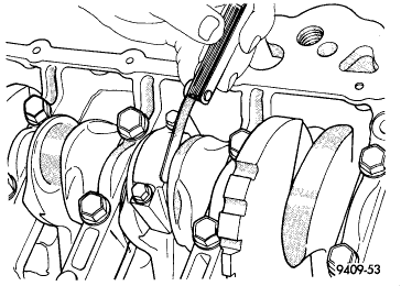
Using a feeler gauge, check connecting rod side clearance.
Crankshaft Journal Tolerances
Crankshaft Main Bearing Journal Diameter 2.2433-2.2439 in
Connecting Rod Journal Diameter 1.7709-1.7715 in
Maximum Out of Round All 0.0006 in
Maximum Taper All 0.0002 in
Bearing Clearance Main Bearings 0.0008-0.0020 in
Connecting Rod Bearings 0.0008-0.0020 in
Crankshaft Endplay 0.0020-0.0070 in
Water Pump Assembly
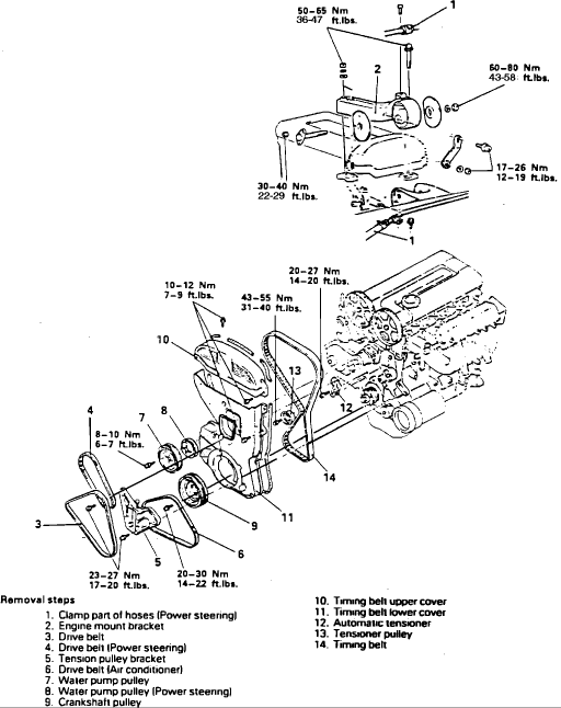
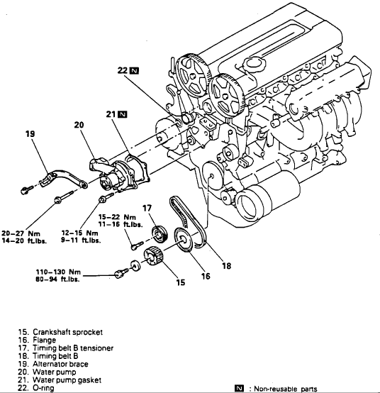
REMOVAL
Remove water pump in numbered sequence, Fig. 77, noting the following:
Remove lower engine compartment cover.
Drain engine coolant as follows:
Place instrument panel temperature control lever in Hot position.
Carefully remove radiator cap.
Remove radiator drain plug.
To remove engine mount bracket, slightly raise and support engine, removing weight of engine from mount.
Remove automatic tensioner, timing belt and timing belt B, refer to TIMING BELT .
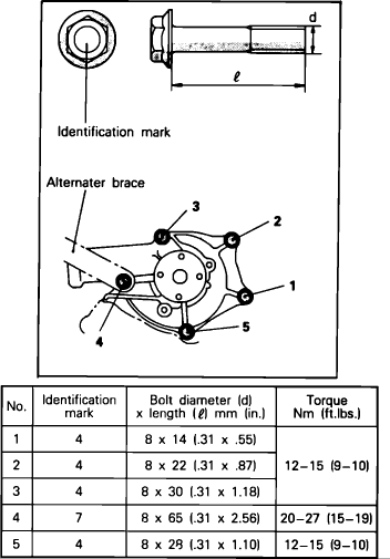
Fig. 78 Water Pump Attaching Bolts.
INSTALLATION
Reverse removal procedure to install, noting the following:
Coat the O-ring (26) with water to ease installation.
Refer to bolt length chart, Fig. 78, when installing water pump attaching bolts.
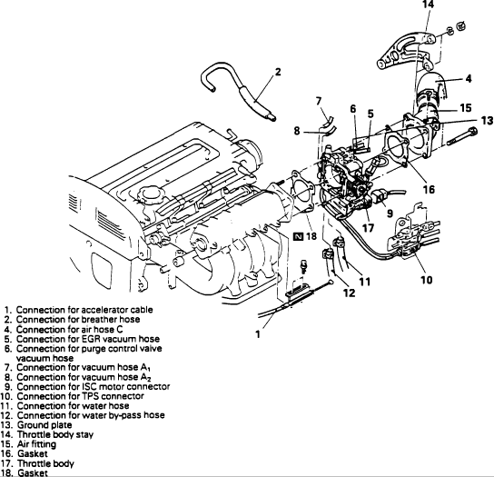
Throttle Body
