i got a header and made this

| 4g61t.org http://4g61t.org/forum/ |
|
| help with microsquirt pnp harness http://4g61t.org/forum/viewtopic.php?f=6&t=39237 |
Page 1 of 1 |
| Author: | whe3ls [ Sat Nov 08, 2014 11:26 am ] |
| Post subject: | help with microsquirt pnp harness |
I finally got my elantra running. I picked up a microsquirt and i would like to use it in my elantra. ive put together most of the harness. but im not sure how to hook up the mpi pins 63,66 and where to get switched power for the microsquirt. can anyone help. |
|
| Author: | Keane [ Sat Nov 08, 2014 12:09 pm ] |
| Post subject: | Re: help with microsquirt pnp harness |
I am using the megasquirt diypnp. The one where they provide a factory style plug that you solder all your connections to in the case so you can use your stock harness. That version is based off the microsquirt board so maybe this will help? https://www.diyautotune.com/diypnp/apps ... 63-mt.html |
|
| Author: | Keane [ Sat Nov 08, 2014 12:28 pm ] |
| Post subject: | Re: help with microsquirt pnp harness |
https://www.diyautotune.com/diypnp/docs ... dapter.jpg check out this image. This is what mine looks like you can see how the lower board gets all the jumpers from the main board which basically just makes all the proper connections to the ecu plug pins. How different is your setup? are you using/integrating the factory harness. I could always take a look at my pinout again if that turns out to be a way to help. |
|
| Author: | whe3ls [ Sat Nov 08, 2014 1:19 pm ] |
| Post subject: | Re: help with microsquirt pnp harness |
this is what i have. http://www.diyautotune.com/catalog/micr ... p-519.html |
|
| Author: | whe3ls [ Sat Nov 08, 2014 1:31 pm ] |
| Post subject: | Re: help with microsquirt pnp harness |
i got a header and made this
|
|
| Author: | Keane [ Sat Nov 08, 2014 2:30 pm ] |
| Post subject: | Re: help with microsquirt pnp harness |
12V Supply to ECU To bring switched 12V to the ECU you will first need to take control of the main relay. Jumper from connectorboard C1 to the "IN" of one of the relay circuits. Jumper from the "OUT" of the same relay circuit to both B3 and B6 on the connectorboard. The resulting output from the main relay will then be brought to the ECU by jumping connectorboard C4 to 12V on the main board. C1 is pin 110 ign switch. Pin b3 is pin66 mpi. Pin b6 is pin 63 mpi. What the above is saying is take power from pin 110 solder it to relay cicuit in and then take two leads from the relay cicuit out to feed pin 63 and 66 essentially powering up the mpi relay. The difference is i have the said relay circuits on my board and you only have the wires coming out of the unit...hmm what is the microsqirts wiring pinout? Are they named or numbered? |
|
| Author: | whe3ls [ Sat Nov 08, 2014 2:36 pm ] |
| Post subject: | Re: help with microsquirt pnp harness |
http://www.microsquirt.info/uswiring.htm |
|
| Author: | Keane [ Sat Nov 08, 2014 3:16 pm ] |
| Post subject: | Re: help with microsquirt pnp harness |
too bad im no expert at all so im probably not helping much. i looked at that link and i see the pin 1 12volt supply wire it says "This connects to a switched 12 Volt supply. Use the ignition switch to control a relay that provides 12 volts to both the MicroSquirt® and the injectors." it seems like we are really close though.... your ign switch pin 110 just needs to power up the mpi relay pin63,66 and then 12v power should be available on pin 107 for powering your microsquirt. thats what mine does except that i have that spot on the board for relay in and out where the ign switch wire goes in and then 2 wires go out to mpi relay 63,66. and finally i power my megasquirt from pin 107 after the mpi relay is energized. so my interpretation to what there saying above is almost like you have to make that happen on the car (since you dont have that little relay board spot like i do) and then you can take power for your unit from pin 107? |
|
| Author: | Keane [ Sat Nov 08, 2014 3:36 pm ] |
| Post subject: | Re: help with microsquirt pnp harness |
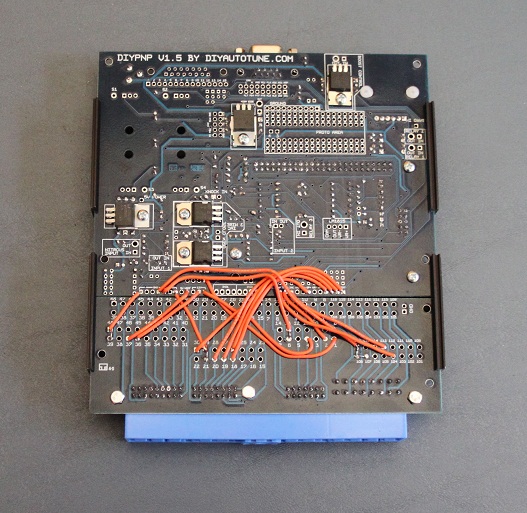
 heres a shot of the relay board spot inside my megasquirt the orange wire on the left is from pin 110ign switch and its going into the relay spot. the two red wires are going out from the relay spot and go to pin63,66 mpi main relay. at that point i guess my ign switch powers up my mpi relay and then provides 12v power to pin 107 where i then get my main switched power fro my megasquirt unit. i know its different for your setup but hopefully kind of understanding the process gets us closer? i dont know what the little relay section is on my board though and im not sure how you would get your ign switch to power up your mpi relays? or does it already? im really not a dsm wiring or wiring expert in general ha ha |
|
| Page 1 of 1 | All times are UTC-05:00 |
| Powered by phpBB® Forum Software © phpBB Limited https://www.phpbb.com/ |
|